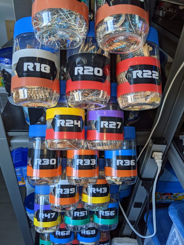
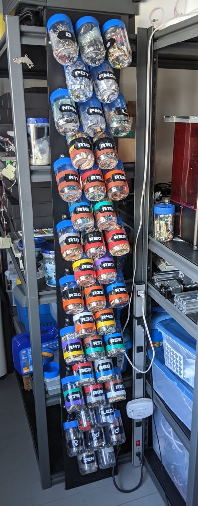
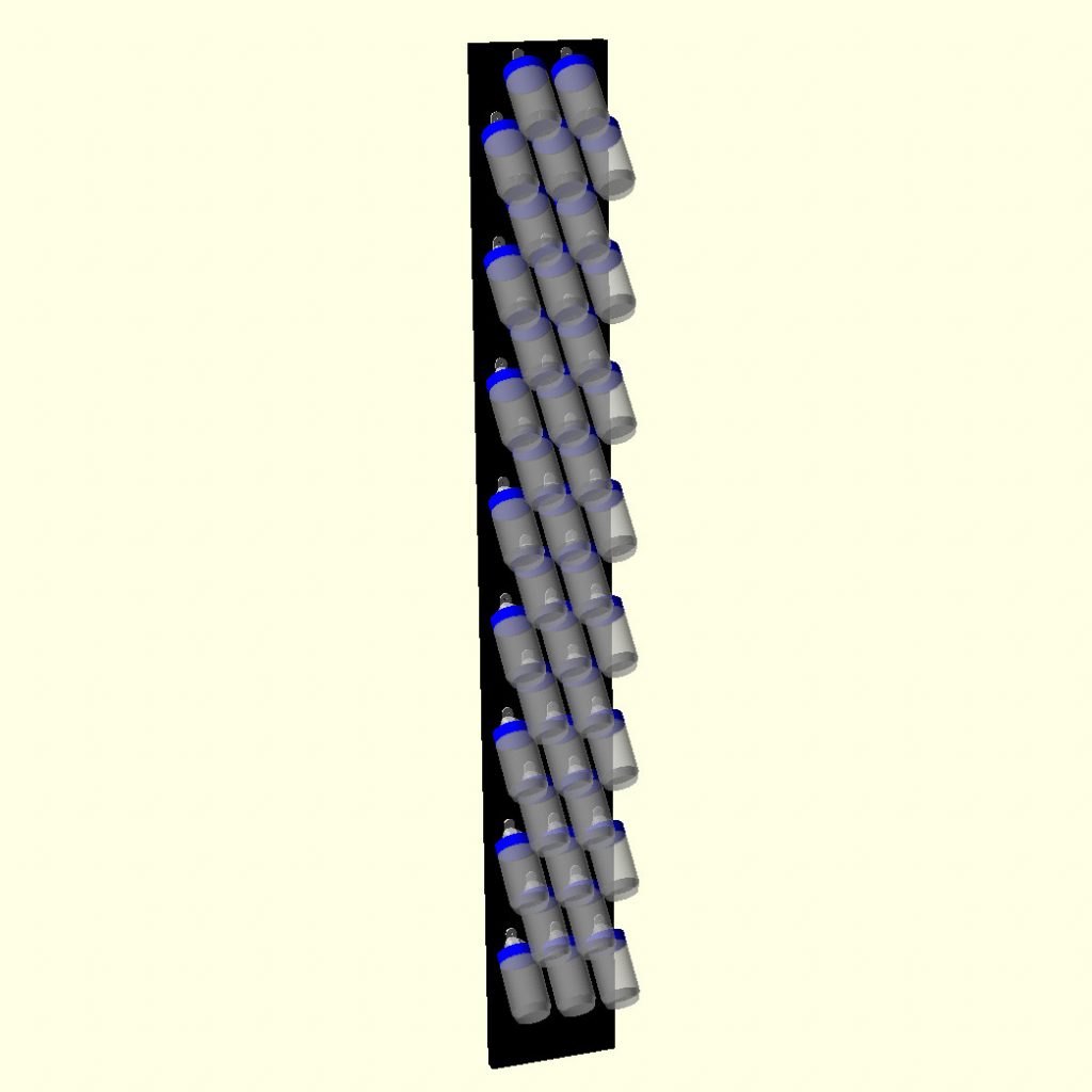
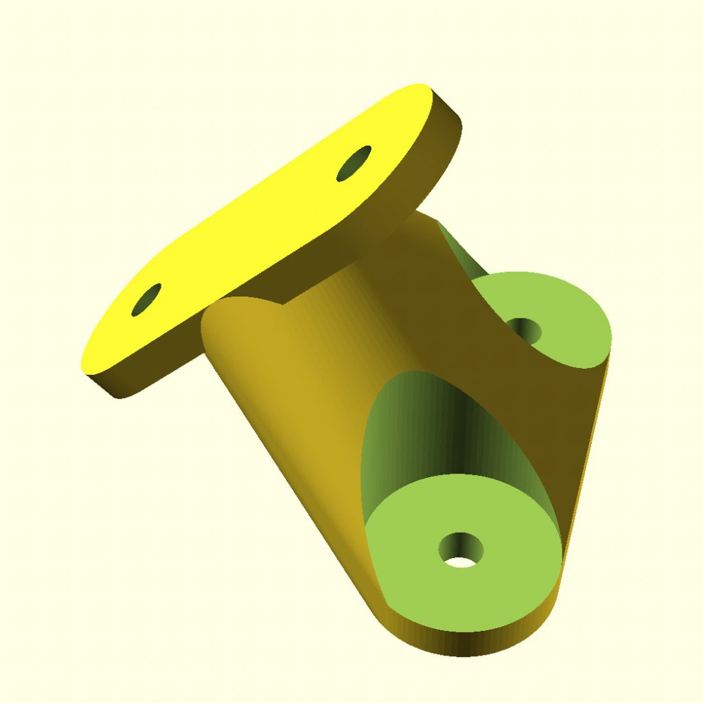
I wanted to store a full E24 through-hole resistor set (and a few other common components), and after looking at different solutions, I decided to go with cheap containers and make something nice out of them. Each peanut butter container has all multiples on one value (ie, R10 has 1ohm, 10ohms, 100ohms, 1kohm, 10kohm, 100kohm, and 1Mohm). Works well, and every container is rigidly screwed to the base, so no accidents and not as much dust.
Making
Mill Calibration
I’ve had some people ask me about calibrating a mill when using grbl, without knowing the steps/revolution of the motor, or the lead screw pitch (or bothering to look up and/or measure them). It’s a pretty simple process, but not all interfaces will make it obvious. Start by moving the mill to a safe position either manually of through whichever control program you use. I start it roughly centered to be on the safe side.
Then connect to the grbl controller directly via a serial console. You can use any serial terminal, I like screen. Don’t forget to replace /dev/ttyUSB0 with your serial port.
screen /dev/ttyUSB0 115200Hit enter a few times if necessary so that grbl returns “ok”. We can now change the variables that control the number of steps generated by grbl per millimeter of movement (steps/mm). grbl variables are assigned numbers, you can find the list on the grbl wiki. You can type $$ (two dollar signs) to get grbl to print the current values of the variables.
We’ll start by calibrating the x axis, so we’ll set the steps/mm variable for the x axis ($100) to 10000. This means that for one millimeter of movement, grbl with output 10000 steps. We also issue a G92 code to make the current position the 0 for the X axis.
$100=10000
G92 X0
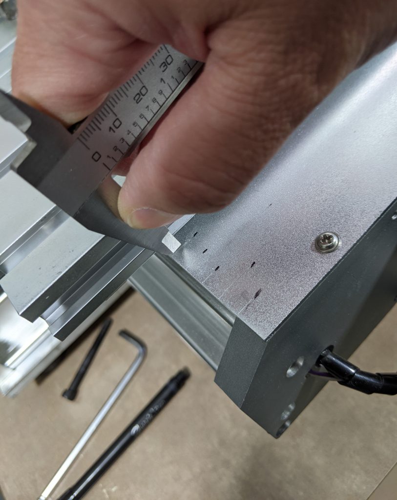
Before moving the machine, make a mark, either with a pen or with a scribe. I use the blade of my calipers, and make a sharpie mark besides each mark to remember where they are. (see first picture at the top)
We now move the machine by one 10000 step units (what the grbl currently thinks is 1mm) by issuing the following gcode command:
G1 X1 F100Once the machine has moved, mark the new location as before. I usually repeat the process again a few times so that I can average the measures at the end
G1 X2 F100
G1 X3 F100
G1 X4 F100
And so on for however many measures you want to take. We can now measure the movement that resulted from each 10000 steps of the motor.
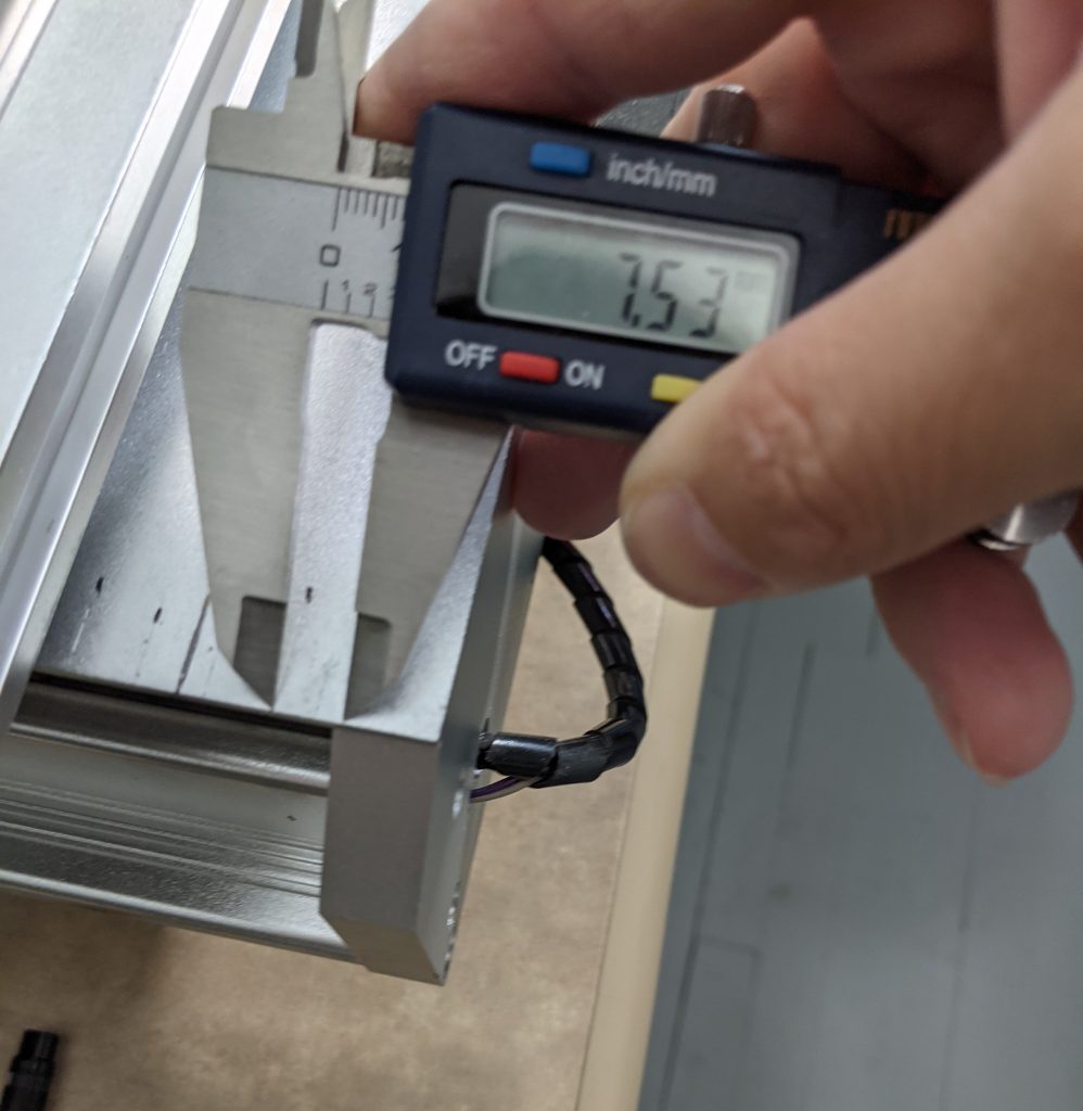
In this example I got an average of roughly 7.5mm per 10000 steps. (see second picture at the top) From this we can find the correct value for the number of steps/mm:
\frac{10000\textnormal{ steps}}{7.5\textnormal{ mm}} = \frac{x\textnormal{ steps}}{1\textnormal{ mm}} \Rightarrow x \approx 1333.33And we can tell grbl to use this value from now on:
$100=1333.33The same process can be repeated for each of the other axes, with $101 being the variable for the Y axis steps/mm and $102 being the variable for the Z axis steps/mm.
As it turns out all three axis of this mill use the same motors, same direct drive configuration and same lead screws, so the steps/mm for all three axis are the same.
Macaroni Filament
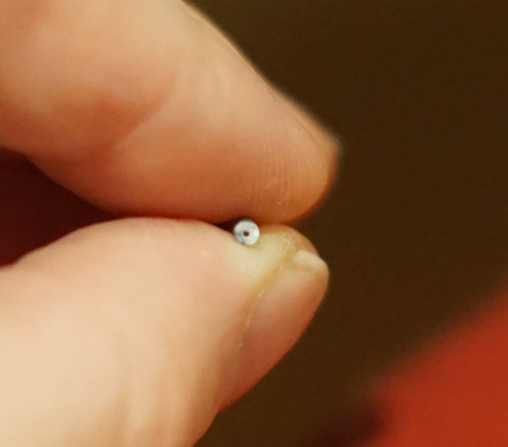
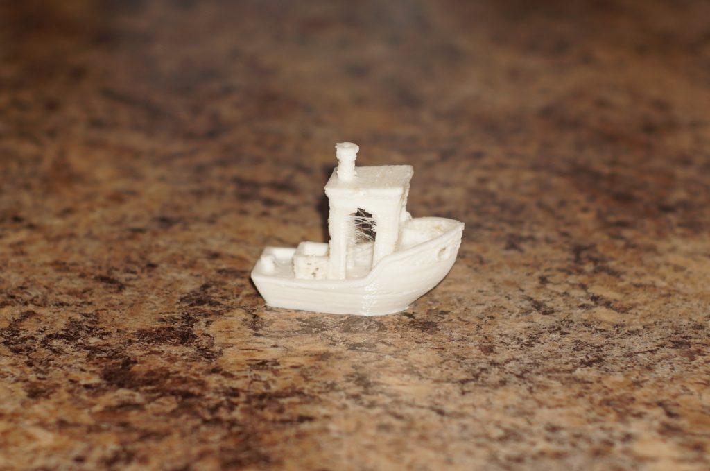
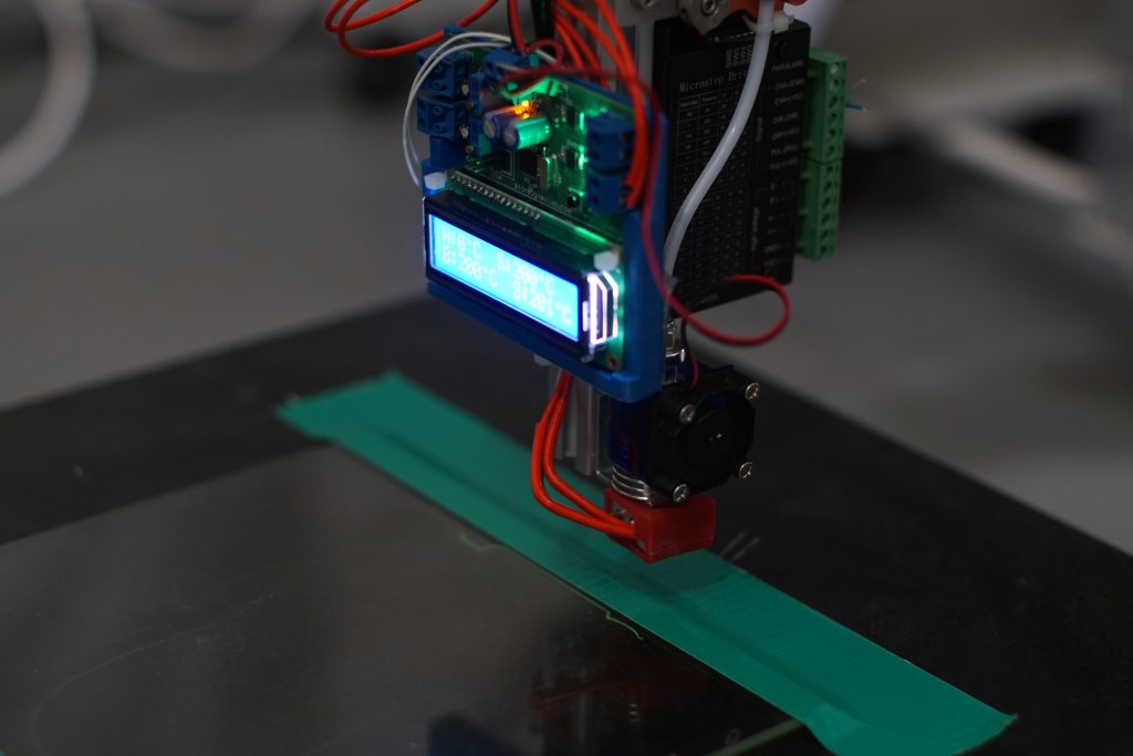
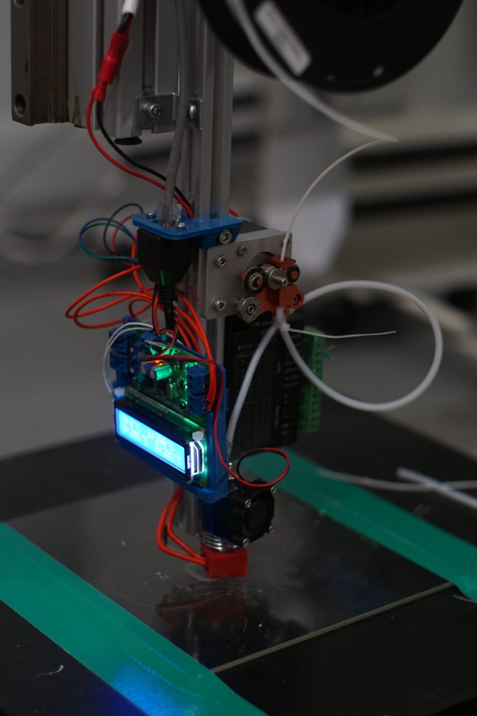
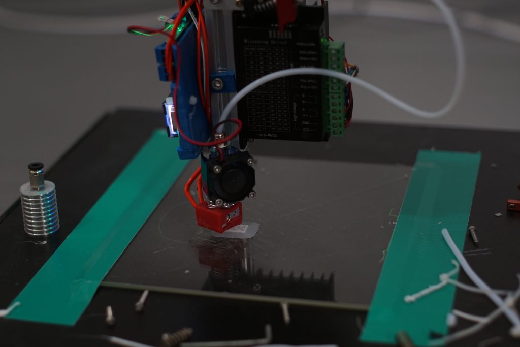
I got a bad batch of filament recently. It kept jamming in the hot end, so after inspection, I noticed that there was a hole running the whole length of the filament…
