Uncategorized
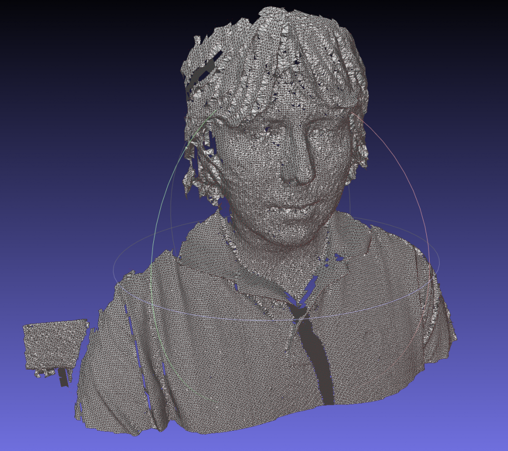
Virtual knots
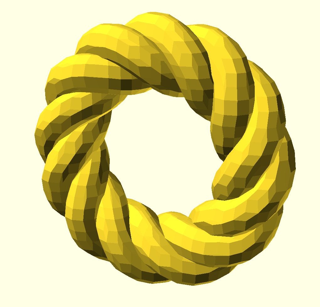
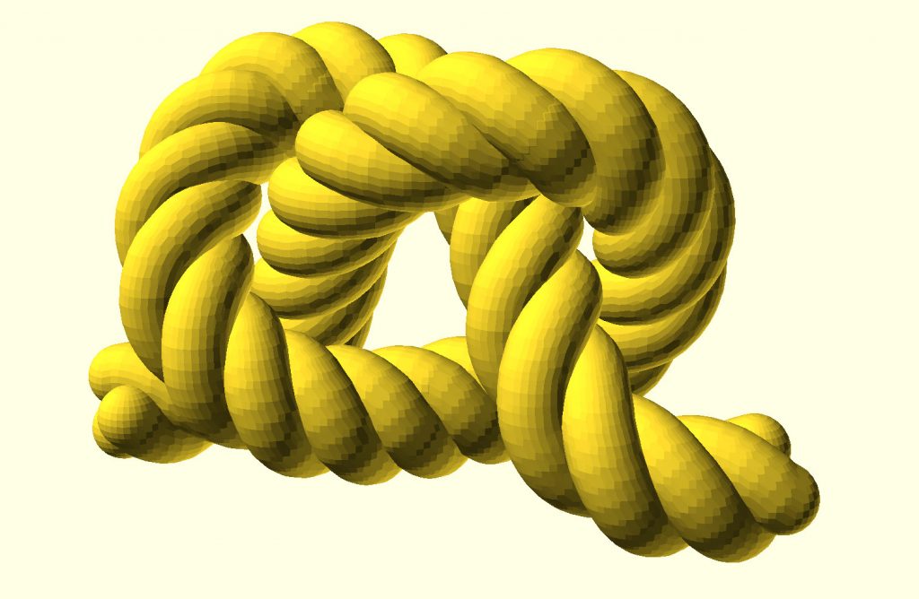
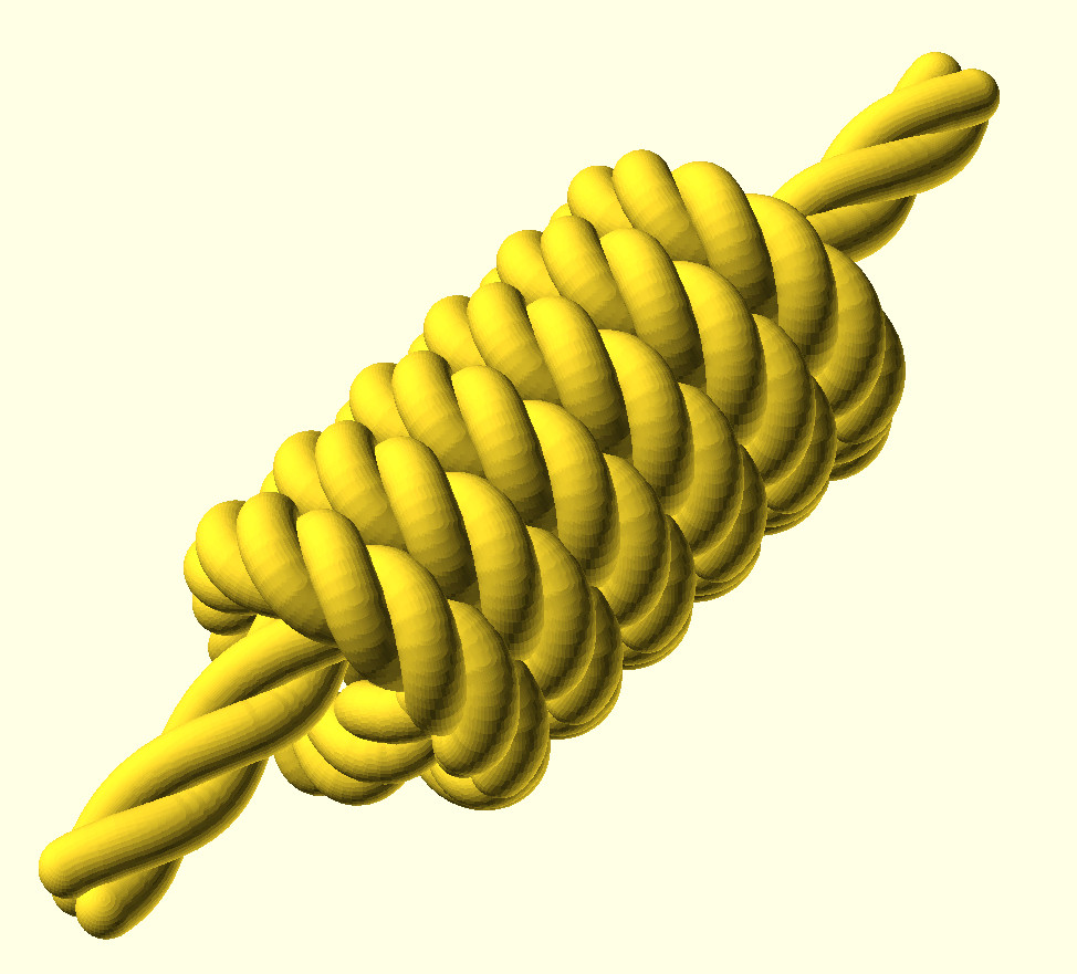
While it might not seem like it, these virtual pieces of rope are closely related to motion paths for the robot arm. Quaternions, interpolation, matrix computations, all of it.
Projection Mapping
Many people have asked how to do some q&d projection mapping, so here’s the rundown:
- Put the projector up, screw it in so it doesn’t move.
- Plug in a computer and open a drawing program (I used Gimp, you can duplicate the working working image and output it to the projector to see the full resolution image as you edit it) and draw over the features of the castle to figure out where things need to be in the videos (position of the clock, the tower, etc). This honestly feels surreal, it looks like you’re painting the castle as you draw over it… I also marked parts of the image I didn’t want to project anything to as the projector covers a bit of the walls beside the table. That’s why there are weird diagonal black bars on each side of the image.
- Load your sketch and the video in Natron and start playing the the corner pin transform until you get something close. The Merge block allows you to put the sketch from the previous step at 50% opacity over the video to align the features, but you can make the sketch transparent when you render the final video. The transform is different for each video as the position of the camera relative to the castle is different depending on where the recording was made. The transform also takes into consideration the relative position of the projector and the Lego castle, which would be different if you did it.
- Export the video
- Play it back. My projector plays videos straight from a usb drive, so that was easy enough…
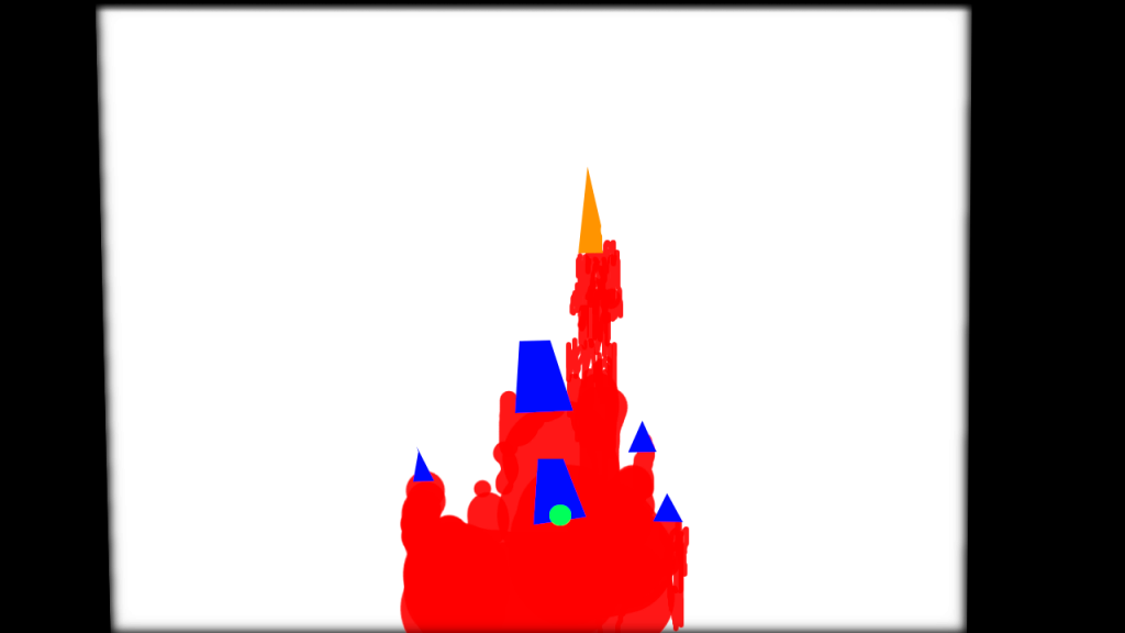
Sketch used to align features 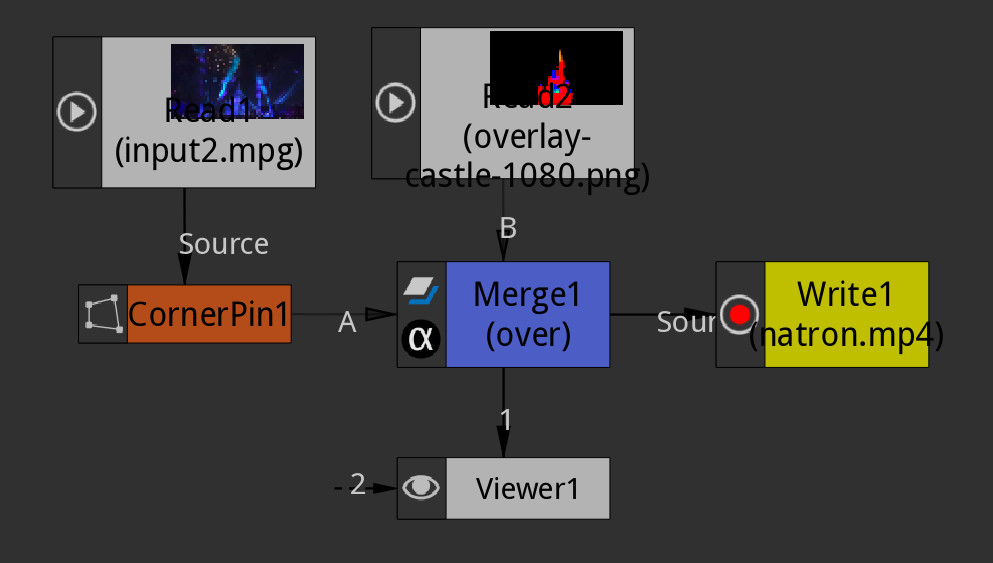
Natron Graph 
Example distorted frame


This is a VERY poor man’s projection mapping, but the illusion is “good enough” for suspension of disbelief. Normally you’d want to calibrate the projector, get the camera projection parameters from the original video and compute the real transformation, but that’s too much work for a Lego set…
Mill Calibration
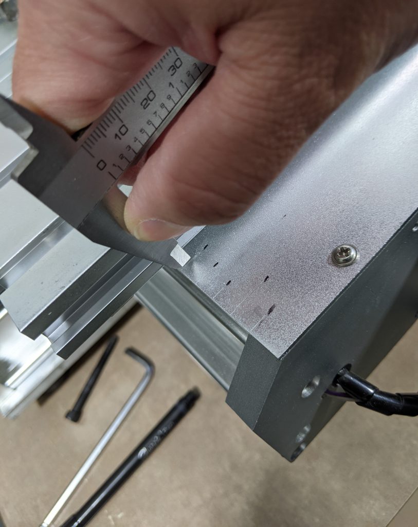
Scribing axis position with a caliper 
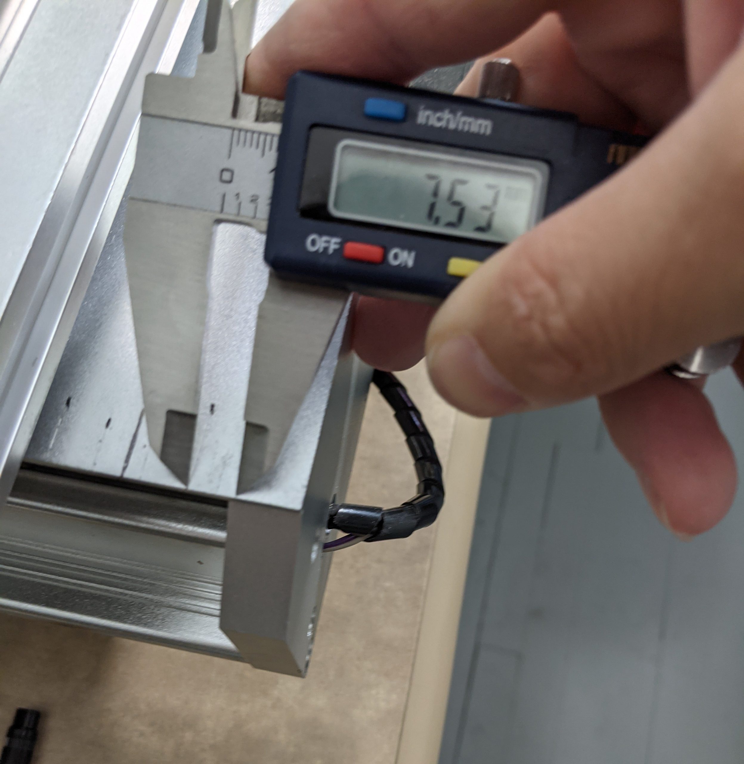
Measuring the distance between marks

I’ve had some people ask me about calibrating a mill when using grbl, without knowing the steps/revolution of the motor, or the lead screw pitch (or bothering to look up and/or measure them). It’s a pretty simple process, but not all interfaces will make it obvious. Start by moving the mill to a safe position either manually of through whichever control program you use. I start it roughly centered to be on the safe side.
Then connect to the grbl controller directly via a serial console. You can use any serial terminal, I like screen. Don’t forget to replace /dev/ttyUSB0 with your serial port.
screen /dev/ttyUSB0 115200Hit enter a few times if necessary so that grbl returns “ok”. We can now change the variables that control the number of steps generated by grbl per millimeter of movement (steps/mm). grbl variables are assigned numbers, you can find the list on the grbl wiki. You can type $$ (two dollar signs) to get grbl to print the current values of the variables.
We’ll start by calibrating the x axis, so we’ll set the steps/mm variable for the x axis ($100) to 10000. This means that for one millimeter of movement, grbl with output 10000 steps. We also issue a G92 code to make the current position the 0 for the X axis.
$100=10000
G92 X0
Before moving the machine, make a mark, either with a pen or with a scribe. I use the blade of my calipers, and make a sharpie mark besides each mark to remember where they are. (see first picture at the top)
We now move the machine by one 10000 step units (what the grbl currently thinks is 1mm) by issuing the following gcode command:
G1 X1 F100Once the machine has moved, mark the new location as before. I usually repeat the process again a few times so that I can average the measures at the end
G1 X2 F100
G1 X3 F100
G1 X4 F100
And so on for however many measures you want to take. We can now measure the movement that resulted from each 10000 steps of the motor.
In this example I got an average of roughly 7.5mm per 10000 steps. (see second picture at the top) From this we can find the correct value for the number of steps/mm:
\frac{10000\textnormal{ steps}}{7.5\textnormal{ mm}} = \frac{x\textnormal{ steps}}{1\textnormal{ mm}} \Rightarrow x \approx 1333.33And we can tell grbl to use this value from now on:
$100=1333.33The same process can be repeated for each of the other axes, with $101 being the variable for the Y axis steps/mm and $102 being the variable for the Z axis steps/mm.
As it turns out all three axis of this mill use the same motors, same direct drive configuration and same lead screws, so the steps/mm for all three axis are the same.